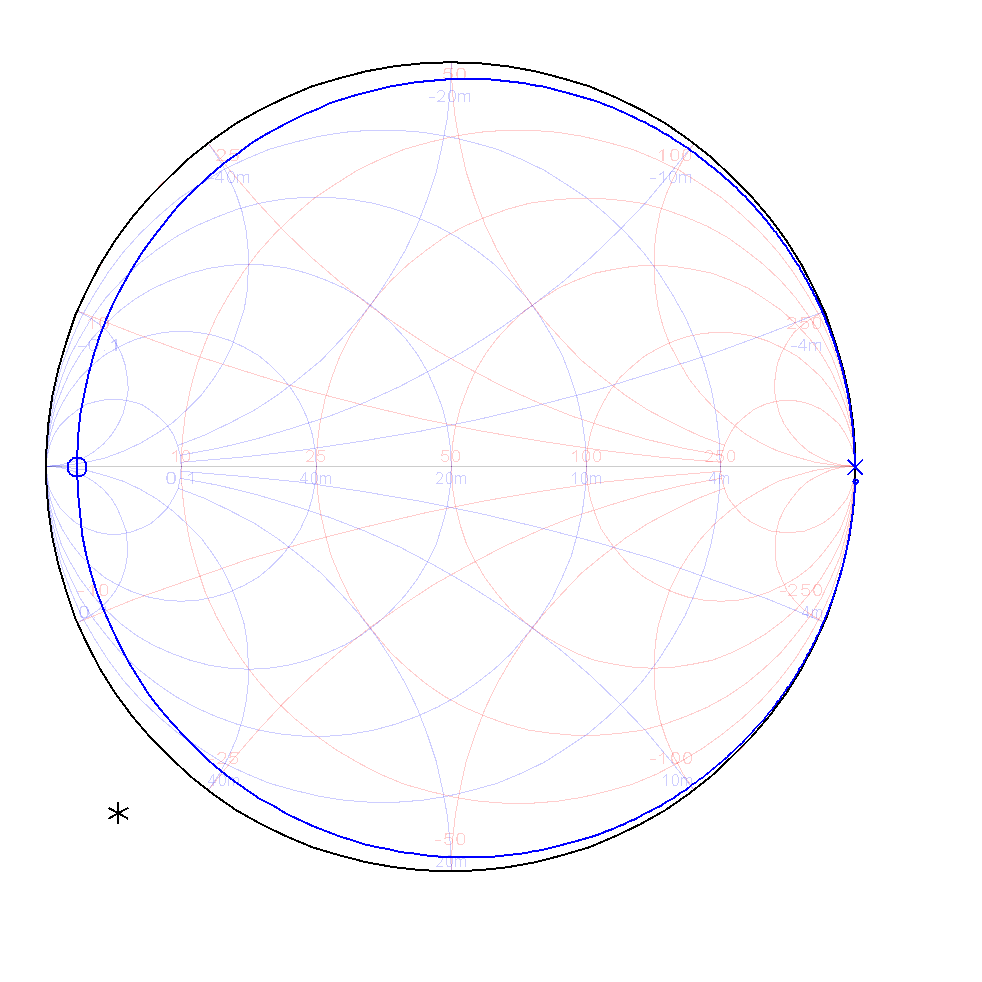

#Transmission line smith chart series#
These are generally termed as the usual type of smith charts as they correspond to impedance and functions in an excellent way even with huge loads constructed of many series components where these are the crucial components in the impedance matching and for other RF corresponding operations. Smith charts are plotted in two dimensions on the intricate reflection coefficient plane and the chart is generally standardized in impedance or admittance or even both through multiple colors in order to differentiate between those parameters and depending on this scaling, these are primarily categorized as three types. This because most RF circuit software’s consists of smith charts for displaying results. As it was known that usage of the smith chart for resolving complicated mathematical problems impose matching issues, but it is still an effective method in explaining how RF frequencies perform at multiple frequency levels.


The chart will be more common in use internal to the regions that have a radius range of 1 or < 1 such as in the cases of stability performance and oscillator design.

At the same time, the device is also used to display various factors like admittance, continual gain outlines, impedance, stability, noise figure, and also shows a detailed analysis of mechanical vibrations. The examples provided here are solved using graphical tools and a printed Smith chart, rather than the computer program, to emphasize the techniques and approximations involved although some of the numerical results listed were obtained with a computerized Smith chart ( smith-chart.m) available with this text ( see page xi).Smith chart is considered as a graphical measuring tool which is constructed mainly for electrical engineers to solve problems related to RF transmission lines and matching devices. A computerized Smith chart can then be used to analyze conditions on lines. Naturally, any chart can also be implemented in a computer program, and the Smith chart has, but we must first understand how it works before we can use it either on paper or on the screen. Some measuring instruments such as network analyzers actually use a Smith chart to display conditions on lines and networks. Although the Smith chart is rather old, it is a common design tool in electromagnetics. As such, it allows calculations of all parameters related to transmission lines as well as impedances in open space, circuits, and the like. The Smith chart is a chart of normalized impedances (or admittances) in the reflection coefficient plane. This has been accomplished in a rather general tool called the Smith chart. Thus, the following proposition: Build a graphical chart (or an equivalent computer program) capable of representing the reflection coefficient as well as load impedances in some general fashion and you have a simple method of designing transmission line circuits without the need to perform rather tedious calculations. You may also recall, perhaps with some fondness, the complicated calculations which required, in addition to the use of complex variables, the use of trigonometric and hyperbolic functions. The reflection coefficient, in turn, was defined in terms of the load and line impedances (or any equivalent load impedances such as at a discontinuity). Voltage, current, and power were all related to the reflection coefficient. The reflection coefficient was used to find the conditions on the line, to calculate the line impedance, and to calculate the standing wave ratio. A look back at much of what we did with transmission lines reveals that perhaps the dominant feature in all our calculations is the use of the reflection coefficient.


 0 kommentar(er)
